
Pegasus Editor enables the creation / modification of the equipment database of each Microwave Link project. Note that it is possible to use the Configurator with a unique equipment database for all the projects; in that Case, the Editor is used to edit the “DEFAULT ” equipment database.
An equipment Database contains all the Microwave systems needed for a project. For each MW Equipment three databases are defined : the Antenna database, the Feeder Database and the Frequency plan database.
A fourth database contains the definitions of all the IRF Matrices (Interference Reduction Factors). There are such matrices for each equipment (Reciprocal Matrices) and IRF Matrices that concern different equipment sharing overlapping frequency bands.
In many cases those latter Non-Reciprocal IRF can be difficult to obtain from the vendor when they concern equipment from different suppliers; However, by compounding a complete ETSI mask database with a powerful convolution processor, PEGASUS EDITOR can generate missing IRF matrixes that would normally be a problem in most conventional planning tools.
MICROWAVE TX & RX PARAMETERS
The System Selector window is Pegasus Editor Main Window and its control center, the menu system gives access to most functions and to the 4 databases.
System Selector common parameters area & menus
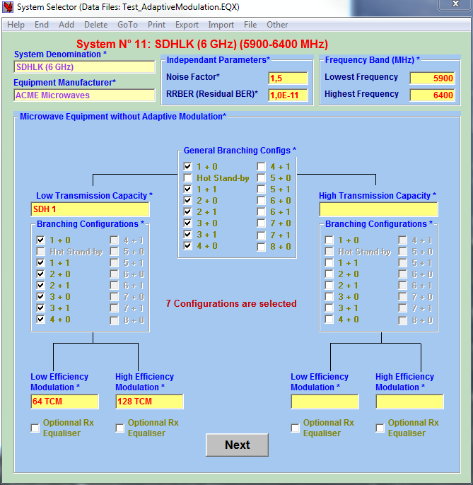
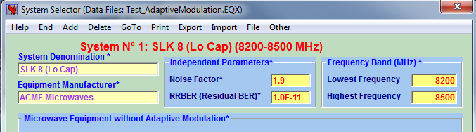
Non-ACM System Selector
The ←System Selector for non-ACM equipment enables:
-
Storing values of general TX & RX parameters
-
Defining Capacity and Modulation
-
defining Branching configurations
-
Add / Delete a Microwave System
-
Navigation between Microwave systems
-
Entering the sequence of viewing the different areas where all the necessary parameters shall be defined.
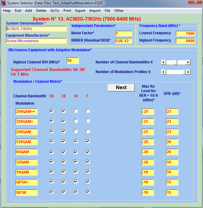
ACM System Selector
System Selector for ACM→ equipment shows general System Parameters such as:
-
Equipment denomination and Manufacturer
-
Noise Factor and RBER
-
Operating frequency Band
-
Modulation Type and the corresponding RX saturation level and the XPIF
-
Modulation / Channel-Bandwidth Matrix that defines the different adaptive configurations (ACM profiles), seven bandwidths and nine modulations may be defined.
The parameters depending only from the Modulation are therefore all defined here.
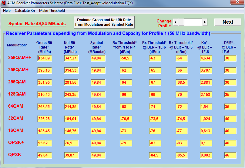
ACM RX parameters Selector
ACM RX parameters depending from Modulation and Capacity are entered in the ACM Receiver Parameters Selector →
They include:
-
Gross and Net Bit Rate,
-
Symbol Rate,
-
the different RX Thresholds,
-
the Kn factor
The Slider at the upper right allows to access the other ACM profiles (if more than one capacity profile is defined for the equipment) , and to enter their RX parameters.
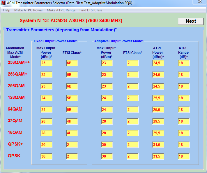
ACM TX Parameters Selector
The TX parameters are to be entered in the ACM Transmitter Parameters Selector→, those parameters do not depend from channel bandwidths: they are the same for all the ACM profiles as Transmitter Parameters depend from Modulation only. Three transmission modes can be chosen:
-
Fixed Output Power Mode: Tx Power is constant and set at the highest value compatible with the highest modulation → Fast response to Fading
-
Adaptive Power Mode: Power changes with modulation → Best Link Budget
-
ATPC Mode is a refinement of Adaptive power: output power depends from the modulation in service and from the receive margin.
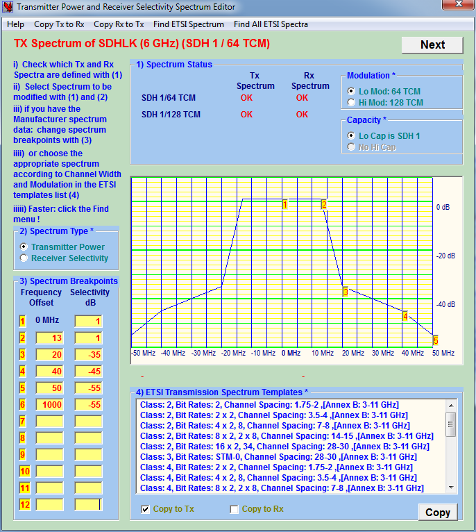 Some essential parameters are sometimes absent from the manufacturer specs. The Editor can propose reasonable values based on the assumption that the MW equipment complies with ETSI EN 302 217-2-1 recommendations. In the ←Transmitter Power & Receiver Selectivity Spectrum Editor, the most relevant TX spectrum ETSI templates are proposed in function of Frequency Band, Modulation and Capacity and the RX selectivity curve is then deducted from the imported TX spectrum template.
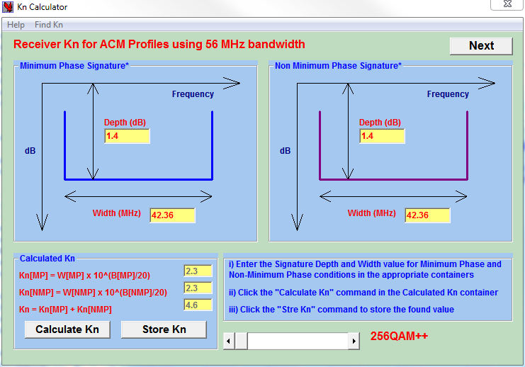
The Kn is essential to calculate the receiver behavior in presence of selective fading is calculated with the Kn Calculator→ if the Receiver Signature Width and Depth are given.
If Signature Width and Depth are absent the Find Kn menu enables to obtain an estimated value based on ETSI specifications and receiver parameters.
ANTENNAS
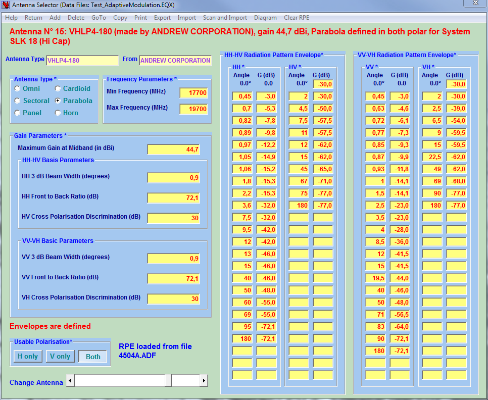
Antenna Selector
Antenna Data can be entered manually in the ←Antenna Selector. The Radio Pattern Envelope (RPE) are defined for VV, VH,HH and HV configurations. It is more easier to use the Import menu to import one antenna data from antenna manufacturer databases files (adf & dat formats). Note that the omnidirectional, Sectoral , Panel, Cardioid and Horn antennas can be defined for Point-MultiPoint applications
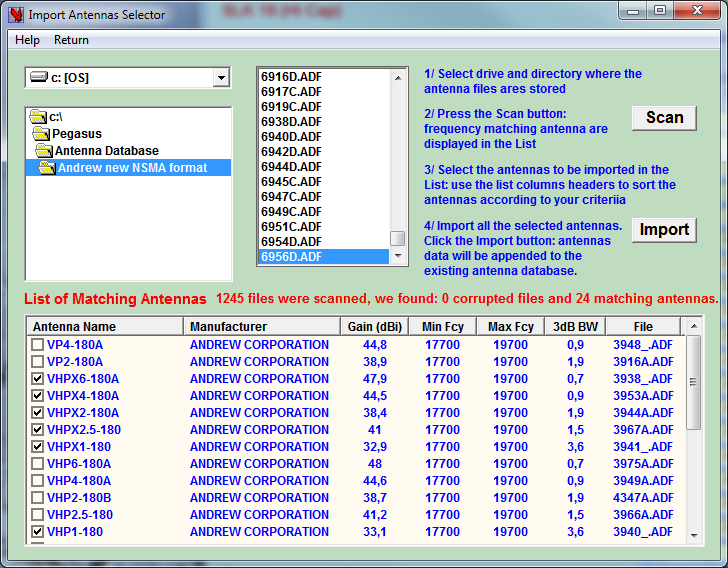 The most efficient is to import all the antennas in one operation using the Import Antenna Selector→. It will scan a complete antenna database directory and propose only antennas compatible with the MW equipment frequency band.
Antenna Diagram Selector
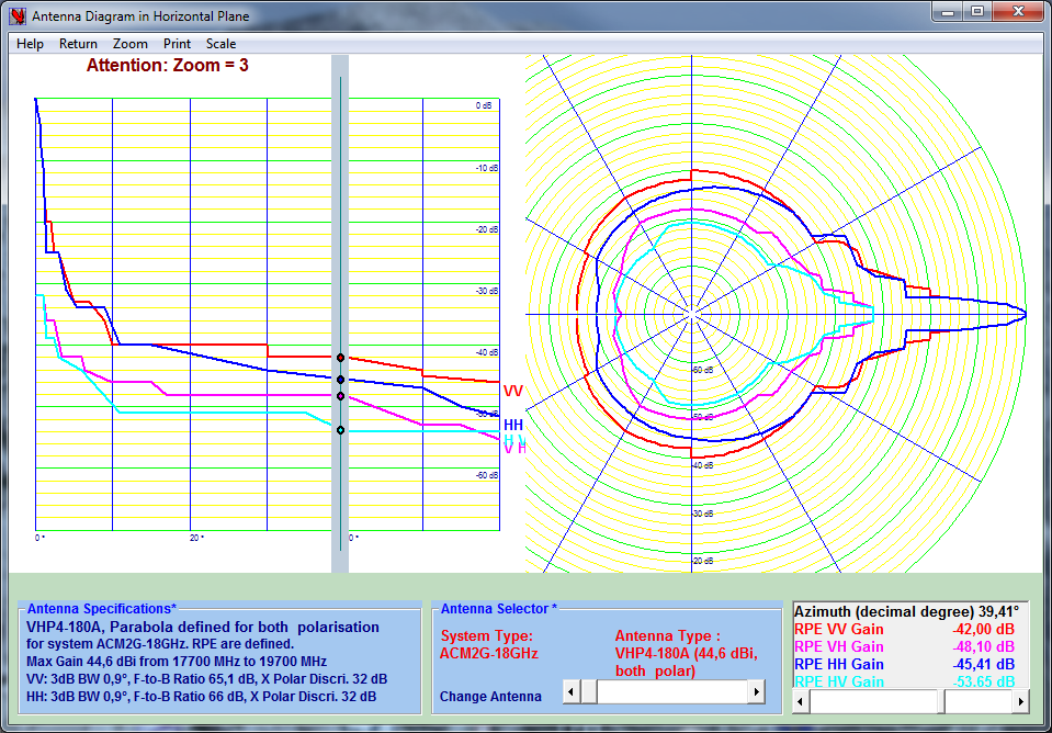
The Antenna Diagram enables to check that the recorded antenna RPE (Radio Pattern Envelopes) are correctly defined. The RPE are displayed for HH, HV, VV and VH configurations.
Select the System and the Antenna to be checked, use the Scale and the zoom to view details. Click the Gain-Azimuth diagram to read gain values.
FEEDERS
Feeder Selector
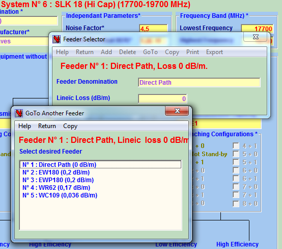
Feeders are very easy to define with the ←Feeder Selector. Note that for those configurations where the antenna is part of the ODU for which there is no feeder; it is convenient to create a “No Feeder” or a “Direct Path” feeder type with 0 dB/m attenuation.
The ←Goto Another Feeder window has its equivalent for the Antenna Selector and the Frequency Plan Selector to enable navigation.
FREQUENCY PLANS
Feeder Selector
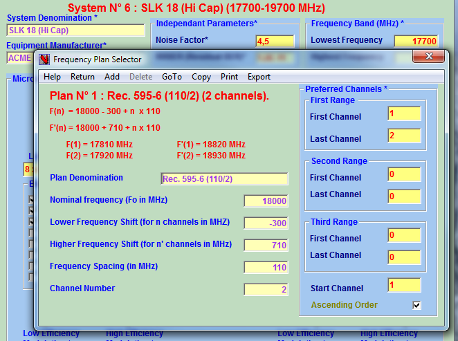
The Frequency Plan Selector→ enables the definition of frequency plans for the current MW system. The formulas canonic form is compliant with ITU-R.
The frequencies for the first and last channels of both half-plan of the current frequency plan are shown to help the user to check the entered formula parameters.
Preferred Channels are subsets of the defined Frequency Plan channels, they might correspond to Channels authorised by the Regulator and defined by a general formulas i.e. “you can use channels 45 to 67 and channels 102 to 135 in the xyz Frequency plan”. Preferred Channels will be used by the Frequency Plan Wizard in the Configurator when performing channel optimization to control interferences .
INTERFERENCE REDUCTION FACTOR (IRF)
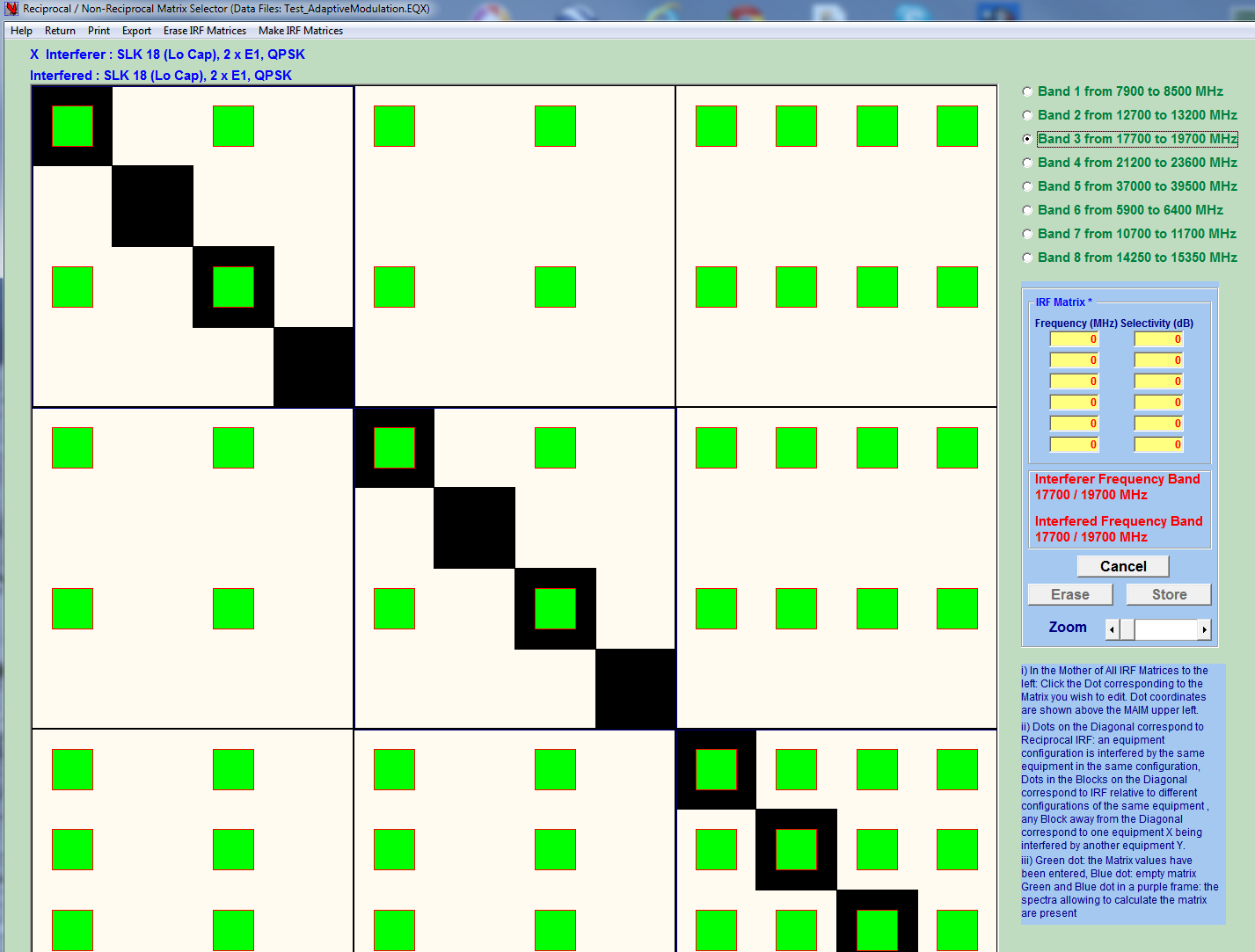
IRF Mother of All IRF Matrices
A dot with a red lining means that the necessary RX & TX spectra are defined and that IRF matrix can be calculated…
It is important to have the capacity to calculate Non-Reciprocal IRF from the equipment spectrum, if only because the manufacturers cannot supply them for cases of interferences with another manufacturer equipment.
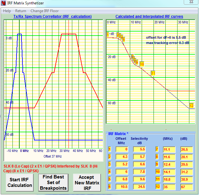
IRF Synthesiser (TX/RX spectrum correlator)
To start the calculation click the “Start IRF Calculation” button: the calculated IRF curve will be traced in red in the right window. Click the “Find Best Set of Breakpoints” button: Pegasus approximate the IRF curve within a 0.3 dB channel with 12 points !.
Note that the Make All Matrices menu will synthetize all the matrices of the current frequency band, provided the TX spectrum and the RX selectivity curves are defined.